The A-scope (1939) — radar's first display
The earliest radars showed a horizontal line on a CRT — time/range on the X axis, return strength on the Y axis. A blip on the line meant a target at that range. The A-scope was simple but gave no bearing information. Operators had to manually rotate the antenna and watch the blip rise and fall to find the direction of maximum return.
The PPI (1944) — the modern radar look
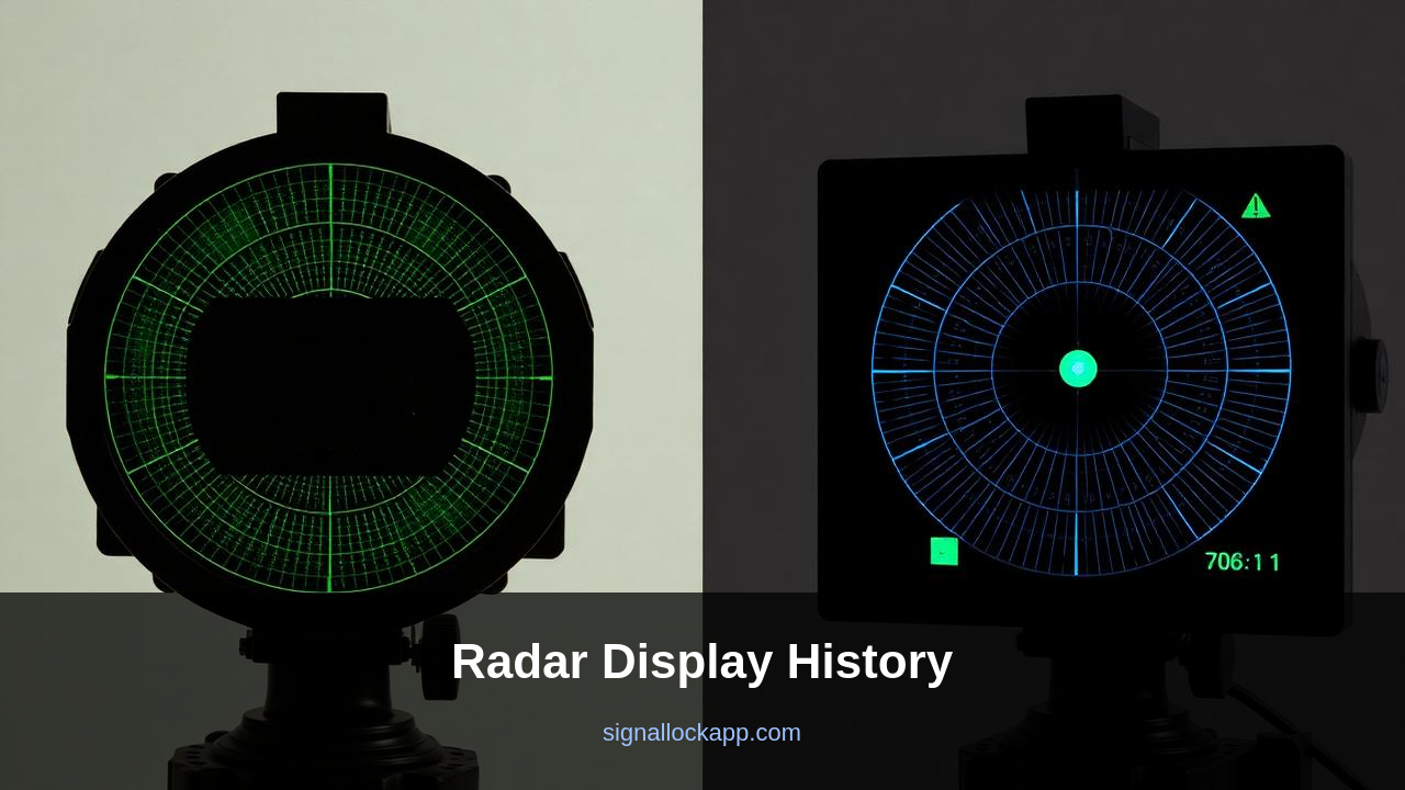
The Plan Position Indicator put the radar at the centre of the screen and painted returns at their actual map position. The antenna rotated; the trace rotated with it; the long-persistence phosphor — P7 yellow-green — kept the previous sweep visible for several seconds while the new one painted over it. That afterglow IS the look of radar.
P7 phosphor was chosen because its decay time happened to match typical antenna rotation rates (4-15 RPM). A coincidence of materials chemistry, not aesthetics, made radar green.
B-scope, E-scope, RHI
The B-scope plotted azimuth on X and range on Y — used by air-intercept radars where the pilot wants to know 'is the target left or right.' The RHI (Range-Height Indicator) plotted range on X and altitude on Y — used by height-finder radars. Each scope evolved to answer a specific operator question.
Modern screens, ancient symbols
Today every radar is digital. The display could look like anything. But air traffic controllers, ship pilots and military operators still see a green PPI with white symbology because the visual language has been refined over four generations of operators and it works. Arcade radar games inherited the look not for nostalgia but because it is genuinely the clearest way to show 'sweep + contacts + history' on a single screen.
The Dark Trace Tube and the Skiatron (1942)
Standard P7 phosphor displays struggled in high-ambient light environments, such as aircraft carrier bridges during daylight. To solve this, British and German engineers independently developed the 'Skiatron' or Dark Trace Tube. Instead of a glowing phosphor, these tubes used a layer of potassium chloride (KCl) crystals that turned magenta when struck by an electron beam. This created a dark image on a light background, which could then be projected onto a large map table using a high-intensity external lamp. This was the first true 'large screen display' for combat information centers, allowing multiple officers to coordinate maneuvers simultaneously.
The physics of the Skiatron introduced a unique limitation: the 'erasing' process. Because the magenta tracks were semi-permanent, the screen could not be cleared by simply waiting for a phosphor to decay. Instead, the rear of the screen had to be heated to approximately 300°C to return the crystals to their transparent state. This thermal reset meant that while the display offered incredible contrast in bright sunlight, it lacked the rapid refresh rate required for high-speed intercepts. By 1950, improved light-shielding hoods and higher-anode-voltage CRTs eventually made the Skiatron obsolete, but its legacy survives in the high-contrast needs of modern cockpit design.
Digitization and the Death of the Sweep
In the mid-1970s, the analog sweep—the rotating line that physically tracked the antenna's position—began to vanish. The introduction of Digital Scan Converters (DSC) allowed the radar's polar coordinates to be mapped into a rectangular bitmapped memory. This allowed the radar image to be displayed on a standard television-style raster monitor rather than a dedicated radar CRT. This transition removed the flickering 'fade-out' effect of phosphor, replacing it with a constant, bright image. However, operators found it harder to judge the age of a return without the natural decay of the old green phosphor, leading engineers to program artificial 'trails' into the software.
Modern glass cockpits utilize Active Electronically Scanned Arrays (AESA), which do not rotate at all. These systems steer the beam at near-instantaneous speeds, meaning the 'sweep' is now a purely aesthetic choice for the user interface. Today, the green glow is often replaced by multi-color overlays where red indicates severe weather and yellow indicates traffic alerts. Despite this, many maritime and military systems still include a 'Legacy Mode' that mimics the P7 phosphor decay of 1944. This is not for nostalgia, but because the human eye is remarkably efficient at detecting slight changes in the density of fading pixels, a skill honed over decades of analog observation.
The Offset PPI and the True Motion Era
By the late 1940s, the standard PPI presented a 'Relative Motion' view, where the observer's ship remained stationary at the center. This forced navigators to perform complex mental vector arithmetic to determine if an approaching blip was on a collision course. If the relative bearing of a contact remained constant while its range decreased, a collision was imminent. To simplify this, engineers developed the 'Offset PPI' and later 'True Motion' displays. By shifting the center point to the edge of the CRT, operators could see much further in the direction of travel, effectively doubling the usable range in the sector that mattered most.
The introduction of True Motion systems in 1956, pioneered by companies like Decca Radar, changed the fundamental logic of the screen. Instead of the world moving past the ship, the ship moved across a fixed coordinate system. This required a mechanical computer to feed speed and heading data from the log and gyro-compass into the CRT deflection coils. For the first time, stationary objects like buoys and coastlines remained fixed on the screen while moving vessels generated distinct 'afterglow' tails, revealing their true headings and speeds at a glance, significantly reducing the cognitive load during narrow-channel navigation.
Trace Intensity and the 'Target Bright-up'
In early analog systems, the visibility of a target depended on 'intensity modulation.' The CRT electron beam was kept just below the threshold of visibility as it swept across the phosphor. Only when a return signal was received was the beam voltage increased, creating a localized bright spot. This created a significant technical challenge: weak signals from small targets often failed to exceed the phosphor's trigger threshold, while strong interference (clutter) from waves would wash out the screen. This led to the development of the Constant False Alarm Rate (CFAR) circuit, which dynamically adjusted the gain to maintain a uniform background noise level.
Refining the 'spot size' was equally critical for resolution. A thick electron beam would merge two close targets into a single blob. Engineers utilized magnetic focusing coils to sharpen the beam, allowing for 'range discrimination' where targets separated by as little as 15 meters could be identified as distinct echoes. In modern digital simulations of these old displays, this analog softening is often artificially replicated; however, in the original hardware, it was a constant battle between maximizing brightness for visibility and maintaining a fine enough trace to prevent the loss of critical spatial data during high-clutter operations.