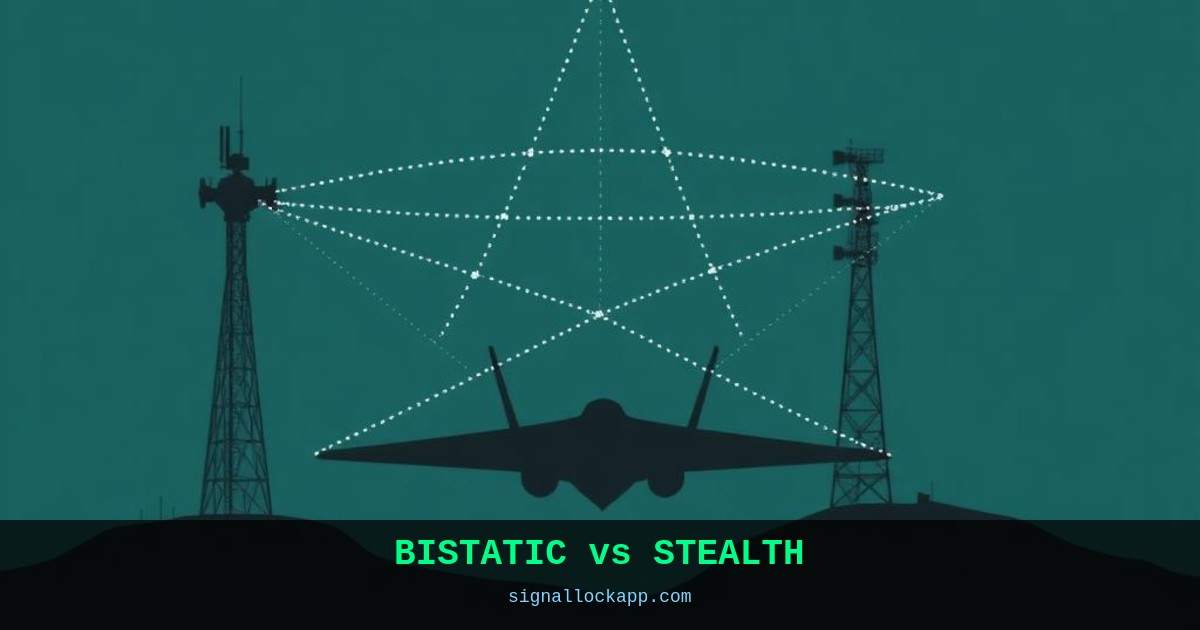
Monostatic vs. bistatic geometry
In a conventional radar, transmitter and receiver share one antenna. The target must reflect energy directly back to the source. Stealth shapes are precisely engineered to avoid this: flat facets, blended curves and absorbent coatings all work against the monostatic return. In a bistatic system the receiver is elsewhere. The reflection angle that stealth optimised against is no longer the one that matters.
Forward scatter
At bistatic angles near 180° — the transmitter behind the target, receiver in front — a phenomenon called forward scatter dominates. Even a stealth aircraft blocks a measurable portion of the signal. The radar cross section in forward scatter can be 1,000× larger than the monostatic RCS. Every TV tower and cell base station becomes a potential illuminator.
Passive bistatic radar
Why build a transmitter at all? Use existing broadcast signals — FM radio, DAB, DVB-T, cell towers — as illuminators. A network of cheap receivers listens for echoes. This is completely covert: no emission, no frequency allocation, no giant radar signature revealing your location. Research systems in the UK, Poland and China have tracked aircraft and ships this way.
Challenges
Synchronising transmitter and receiver in time and frequency is hard. The baseline geometry changes constantly as platforms move. Multipath from terrain and buildings corrupts the signal. And the noise floor is higher when you don't control the transmitter power. But for detecting stealth, these trade-offs are worth it.
The Bistatic Theorem and Cross Section
The effectiveness of bistatic radar is rooted in the Bistatic Theorem, originally proposed by Kell in 1960. It states that the bistatic radar cross section (RCS) is approximately equal to the monostatic RCS measured at the bisector of the bistatic angle. However, this approximation fails as the angle widens toward the forward-scatter region. In these geometries, the target's physical size and shape become the dominant factors rather than its specialized absorbent coatings. This transition shifts the detection problem from electromagnetic absorption to physical diffraction, rendering traditional Radar Absorbent Material (RAM) significantly less effective against a sufficiently dispersed receiver network.
Moreover, the geometric diversity of a multistatic configuration—using multiple receivers for a single transmitter—creates a 'look-through' capability. While a stealth airframe like the F-22 or B-2 is designed to minimize its monostatic return to within +/- 0.5 degrees of the incident beam, it cannot simultaneously suppress reflections in all directions. By positioning receivers at angles optimized for the target's predicted flight path, operators can capture the 'glint' or specular reflections that stealth platforms intentionally deflect away from the original radar source, effectively mapping the target through its own redirection of energy.
Historical Implementation: Operation Orchard
The practical utility of bistatic principles was notably demonstrated during 'Operation Orchard' in 2007. While often discussed in terms of electronic warfare and 'Suter' network penetration, the incident highlighted the vulnerability of integrated air defense systems to unorthodox signal geometries. Modern systems like the Vera-NG or the German Hensoldt TwInvis further evolve this by utilizing the 'shadow' of a target. These systems do not rely on a reflection in the traditional sense; instead, they detect the momentary phase disturbance and signal blockage as an aircraft passes between a commercial broadcast tower and a localized receiver array.
Historical developments in bistatic sensing date back to the 1930s with the British 'Chain Home' system, which utilized separate transmitter and receiver sites. While this was initially a result of technological limitations regarding duplexing, it unintentionally provided a resilient architecture against early electronic countermeasures. Today, the challenge has shifted from basic detection to precise localization. Synchronizing high-stability atomic clocks—such as Rubidium standards—allows modern receivers to calculate the Time Difference of Arrival (TDOA) with enough precision to generate a firing-quality track on targets that would remain invisible to synchronized monostatic arrays.
The Bistatic Range Ambiguity
In a monostatic system, the time delay between pulse transmission and reception directly correlates to a simple linear distance. Bistatic geometry complicates this through the 'bistatic triangle' formed by the transmitter, target, and receiver. The system measures the total path length—the sum of the distance from transmitter to target and target to receiver. This results in an iso-range contour shaped as an ellipse with the transmitter and receiver at the foci. To determine a precise location, the receiver must distinguish the direct signal from the transmitter (for synchronization) from the reflected echo, often requiring high-precision atomic clocks or dedicated baseline links to resolve the timing offset.
This spatial separation introduces the 'dead zone' along the baseline between the two stations. If a target flies directly between the transmitter and receiver, the time delay approaches zero relative to the direct signal, making detection nearly impossible due to masking by the primary transmission. However, as the target moves away from this baseline, the unique geometry allows for the detection of reflections from facets of a stealth aircraft that were specifically angled to avoid monostatic return. By utilizing multiple receivers at varying baselines, a system can construct a multistatic mesh that effectively negates the geometric advantages of radar-absorbent material and faceted airframes.
The Klein-Heidelberg System
Historical precedents for bistatic operation date back to the Second World War with the German 'Klein-Heidelberg' system. Deployed in 1943, this was the first operational passive bistatic radar. It did not have its own transmitter; instead, it utilized the pulses emitted by British Chain Home radar stations across the English Channel. By intercepting the British signals and measuring the delay of the echoes bouncing off Allied bombers, the German military could track incoming raids without emitting any radio frequency energy themselves. This made the Klein-Heidelberg stations immune to Allied electronic countermeasures and anti-radiation missiles of the era.
The technical achievement of the Klein-Heidelberg was remarkable given the lack of digital processing. Operators used a specialized cathode-ray tube display to manually synchronize with the British pulse repetition frequency. Despite the primitive hardware, the system provided a detection range of up to 450 kilometers, depending on the altitude of the target. It proved that the fundamental weakness of stealth—the fact that signals must go somewhere even if they do not return to the source—could be exploited using the enemy's own infrastructure. Modern passive Coherent Location (PCL) systems are direct technological descendants of this 1940s innovation.