The big four
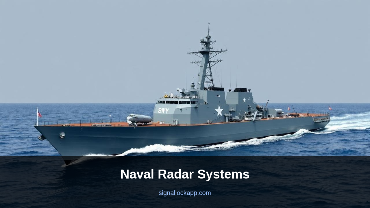
Most warships carry four radar categories. Long-range air search (low frequency, 200+ km range, finds incoming aircraft and missiles). Surface search (X-band, 50 km range, finds ships and small craft). Navigation (10 km, mandatory for safe operation). Fire control (high-precision, narrow beam, guides each weapon). Aegis cruisers and destroyers fold all of this into a single SPY-1 or SPY-6 phased array.
Why Aegis was revolutionary
Before Aegis, a Soviet anti-ship missile attack could saturate a US warship's mechanical radars and fire-control directors. Aegis (deployed 1983) replaced them with four fixed phased-array faces and a single integrated combat system. One ship could now track 100+ targets and guide dozens of missiles simultaneously. Every modern guided-missile warship in NATO, Japan and South Korea uses Aegis or a copy of the idea.
Sea-skimming missiles and clutter
An anti-ship missile flies 5 metres above the wave tops at Mach 2 to stay below the radar horizon. Detection range against a sea-skimmer is 20-30 km — about 30 seconds of warning. Sea clutter — radar returns from waves — drowns out the target unless the radar uses Doppler filtering and ridiculous processing horsepower. The 2024 Houthi anti-ship missile attacks in the Red Sea were a real-world test of all this.
Why ships go quiet
A radiating radar is also a beacon. In wartime, ships often run EMCON (Emission Control), shutting down their radars and relying on AWACS, satellites and other ships' datalinks. The trade-off is between seeing and being seen — exactly the same problem an arcade radar player has.
The dual-band dilemma
Modern naval architecture faces a fundamental physics conflict known as the dual-band dilemma. For long-range volume search, lower frequencies like S-band (2-4 GHz) are preferred because they suffer less atmospheric attenuation and can detect smaller targets at greater distances. However, for precision missile guidance and tracking sea-skimmers, higher frequencies like X-band (8-12 GHz) are required for their superior angular resolution. While the US Navy's Zumwalt-class was originally designed to integrate both into a single Dual Band Radar (DBR) suite, the extreme cost and complexity of synchronizing two different phased-array systems led to the removal of the S-band component on later hulls, illustrating that even with unlimited budgets, radar integration remains a compromise.
To solve this without two separate massive arrays, engineers developed GaN (Gallium Nitride) semiconductors. Unlike older GaAs (Gallium Arsenide) technology, GaN can handle significantly higher power densities and thermal loads. This allowed the development of the AN/SPY-6 Air and Missile Defense Radar (AMDR), which provides 30 times the sensitivity of the classic SPY-1. This jump in raw power allows a single S-band array to perform high-resolution tasks that previously required a dedicated X-band director. This shift represents the most significant change in naval semiconductor physics since the transition from vacuum tubes to solid-state electronics in the late 1970s.
The horizon problem and the CEC solution
No matter how powerful a radar is, it cannot see through the Earth. For a ship-mounted sensor, the radar horizon against a missile flying at 10 meters is roughly 25 to 30 kilometers. By the time a defender sees a supersonic threat, the timeline for a successful intercept is compressed to seconds. To break this geometric cage, modern navies use Cooperative Engagement Capability (CEC). This protocol links sensors across multiple platforms—ships, E-2D Hawkeye aircraft, and F-35 fighters—into a single high-speed data network. It allows a cruiser to fire a missile at a target it cannot see, using the tracking coordinates provided by a remote aircraft flying hundreds of miles away.
This 'engage on remote' capability effectively pushes the radar horizon out by hundreds of kilometers. Historically, the 1982 Falklands War demonstrated the lethality of this gap, where HMS Sheffield was lost to an Exocet missile partly because it lacked airborne early warning to see over the horizon. Today, the integration of Link 16 and CEC means that a single ship no longer acts as an island. For a modern task force, the 'radar' is no longer a physical antenna on a mast, but a distributed cloud of data points where the shooter and the sensor are rarely the same hardware.
The transition to Active Electronically Scanned Arrays (AESA)
While the original Aegis SPY-1 system used passive phased arrays (PESA), modern surface combatants like the Flight III Arleigh Burke class are transitioning to Active Electronically Scanned Arrays (AESA). In an AESA system, such as the Raytheon SPY-6, the single central transmitter is replaced by thousands of individual Transmit/Receive (T/R) modules. Each module acts as its own tiny radar unit, allowing the ship to generate multiple beams simultaneously at different frequencies. This capability is critical for electronic counter-countermeasures (ECCM), as it makes the radar significantly harder to jam. If a few modules fail or are damaged, the array suffers only a slight degradation in performance rather than a total system failure.
The shift to AESA also solves the problem of 'dwell time' on target. Traditional rotating radars scan the entire 360-degree horizon at a fixed rate, meaning they only see a specific threat once every few seconds. With AESA, the beam can be steered near-instantaneously to track a high-priority target while continuing to scan for new threats elsewhere. This high update rate is essential for intercepting hypersonic glide vehicles that can maneuvers significantly within the span of a single mechanical rotation. By 2030, the ability to software-define these radar beams will be the primary metric of naval power, shifting the focus from the number of missiles carried to the processing power of the radar suite.
IFF and the danger of blue-on-blue resets
In the chaotic environment of a naval engagement, the radar return of a friendly F/A-18 and an enemy cruise missile can appear dangerously similar on a raw display. This necessitates the Identification Friend or Foe (IFF) system, an interrogator-responder mechanism that works alongside the primary search radar. Developed from the WWII-era 'Christie' and Mark III systems, modern IFF uses encrypted pulses (Mode 5) to verify identity. If a contact does not return the correct cryptographic handshake, it remains 'bogey' or 'hostile.' The technical challenge lies in the beamwidth; if the IFF antenna has a wider beam than the primary radar, it may accidentally validate a hostile target flying in close proximity to a friendly aircraft.
Historically, IFF failures have led to catastrophic friendly-fire incidents, such as the 1988 shooting down of Iran Air Flight 655 by the USS Vincennes. In that instance, the crew misinterpreted Aegis data, believing a civilian airliner was an attacking F-14. Since then, naval radar integration has moved toward 'NCTR' (Non-Cooperative Target Recognition). NCTR uses high-resolution radar returns to identify the specific engine blade modulation or airframe geometry of a target without relying on a radio response. This layering of active IFF and passive NCTR ensures that even in a heavy electronic warfare environment, the commander has a high-confidence picture of the battlespace before pulling the trigger.