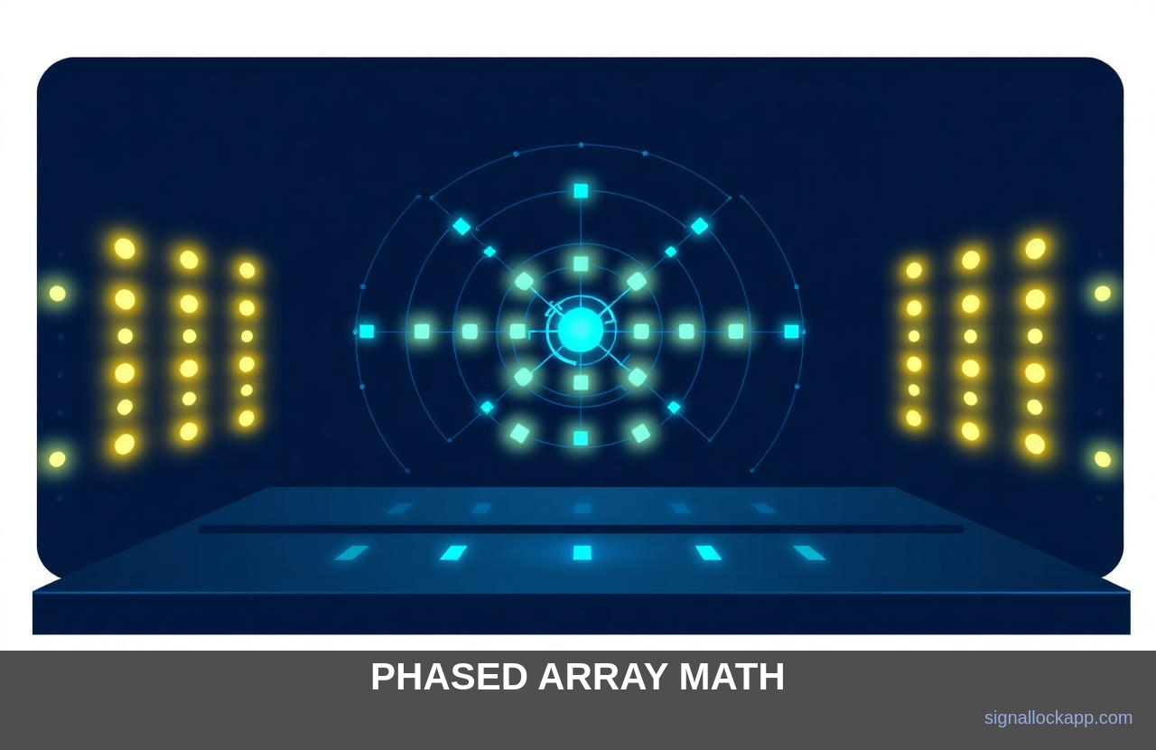
Constructive interference
When two wave sources are in phase, their peaks add. Out of phase, they cancel. A phased array uses this on a grand scale: by delaying each antenna's signal by a precisely calculated amount, you make the peaks line up in the direction you want — and cancel everywhere else.
The phase formula
For an array spaced d apart at wavelength λ, the phase shift needed to steer by angle θ is Δφ = 2π · (d / λ) · sin(θ). Modern chips compute this for thousands of elements every microsecond.
AESA — active electronically scanned array
Each element has its own transmit/receive module. If one fails, the array still works at slightly degraded gain — graceful degradation that mechanical radars can't match. F-35's APG-81 has about 1,200 such modules.
Multi-beam operation
A phased array can form several beams at once: search one volume, track three targets, jam a fourth — all in parallel. This is the killer feature that pushed every modern fighter, AWACS and missile-defence system to phased arrays.
Sidelobe suppression and windowing
A common challenge in array design is the suppression of sidelobes—spurious beams of energy that radiate in unintended directions. If every element in the array transmits at equal power, a predictable diffraction pattern emerges, including 'grating lobes' that can cause ghost targets or reveal the radar's position to adversaries. These secondary peaks are physically inevitable in a uniform linear array, but engineers mitigate them through a process called tapering or windowing. By modulating the amplitude of the signal across the face of the array, they can significantly dampen these outliers.
In practice, this means the elements at the center of the antenna cluster transmit at higher power levels than those at the peripheral edges. While this slightly reduces the total gain and widens the main beam, the trade-off is a much cleaner signal profile. Modern digital beamforming allows for dynamic weighting, where the radar can instantly shift its amplitude distribution to prioritize either maximum range or maximum clutter rejection. This mathematical precision ensures that the radar only 'sees' what it is pointed at, rather than being blinded by its own stray energy reflections.
The PAVE PAWS legacy
The transition from mechanical to phased array systems was solidified by massive Cold War installations like the AN/FPS-115 PAVE PAWS. Commissioned in the late 1970s, these dual-faced arrays standing ten stories tall were designed to detect Submarine-Launched Ballistic Missiles (SLBMs). Unlike the rotating 'dish' radars of the era, PAVE PAWS used two fixed, 30-meter faces tilted at roughly 20 degrees. It demonstrated that a static structure could cover a 240-degree field of view by cycling through thousands of unique phase configurations in milliseconds, a feat impossible for any physical gimbal.
Beyond missile defense, these installations proved that phased arrays could track hundreds of distinct objects simultaneously. By interleaving pulses—sending one pulse to track a satellite and the next to scan the horizon for a missile—the system performed the work of multiple dedicated radars. This multi-role capability eventually scaled down from the concrete structures of Cape Cod to the nose cones of modern fighter jets. Today, the same principles of beam agility allow a single radar system to provide navigation, weather avoidance, and fire control without a single motor turning.
The challenge of grating lobes
While constructive interference forms the main beam, secondary peaks called grating lobes can appear if the antenna elements are spaced too far apart. For a phased array to steer a beam uniquely across a full hemisphere, the physical distance between individual radiator elements must be less than half the wavelength at the highest operating frequency. If the spacing exceeds this λ/2 threshold, the array generates unintentional duplicate beams in other directions, wasting power and creating massive targets for electronic interference. Engineers must balance this tight physical packing against the need for thermal management and signal routing.
In higher-frequency bands like X-band (8–12 GHz), this math dictates a spacing of roughly 1.5 centimeters between modules. Crowding thousands of high-power Gallium Nitride (GaN) amplifiers into such a compact frame creates a thermal density comparable to a high-end CPU, requiring liquid cooling systems in modern fighter aircraft. This is why the physical design of an AESA is as much a mechanical and thermal engineering feat as it is an electromagnetic one, as any deviation in phase caused by thermal expansion can degrade the beam's precision.
The Patriot radar and the move to PESA
Before the modern AESA took over, the Passive Electronically Scanned Array (PESA) defined the Cold War era's most advanced air defense systems. The AN/MPQ-53 radar, part of the MIM-104 Patriot system deployed in the 1980s, utilized a single central microwave source—a traveling wave tube (TWT)—rather than individual amplifiers for every element. This single-source signal was routed through thousands of ferrite phase shifters. While less resilient than modern active arrays, this design allowed the Patriot to track over 100 targets simultaneously and guide multiple missiles at once without the lethargy of a rotating dish.
This transition from mechanical rotation to electronic steering was vital for countering the saturation attacks envisioned during the 1970s. Earlier systems like the Nike Hercules relied on multiple separate radars to track the target and the interceptor separately, which limited the number of engagements a single battery could handle. By adopting electronic phase control, the Patriot system could hop its beam across the sky in milliseconds, effectively performing the work of four distinct mechanical radars. This operational agility remains the baseline requirement for intercepting high-speed maneuvering threats today.