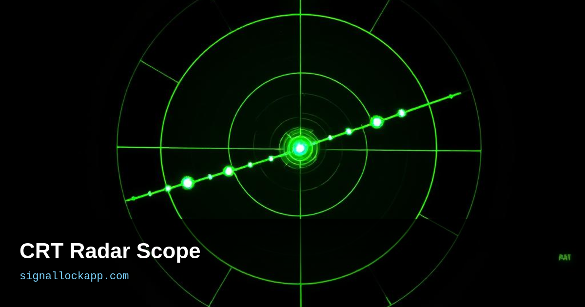
Plan Position Indicator (PPI)
The classic radar screen: a rotating line sweeps from centre to edge like a clock hand, brightening wherever an echo returns. The antenna rotates in sync. After one sweep the screen shows a map of everything around the station. Persistence phosphor leaves the blips visible for a few seconds, so the operator sees a complete picture even though the beam only passes each target once per rotation.
Phosphor chemistry
Short-persistence phosphors (P1, P31) for fast-updating tactical displays. Long-persistence phosphors (P7, P14) for search radars, where the operator needs the target to stay visible for several seconds after the sweep passes. Colour phosphors (rare in radar, common in TV) never caught on because radar didn't need colour — it needed contrast and speed.
A-scope and B-scope
Before PPI, there was the A-scope: a horizontal line with vertical blips — distance on the x-axis, signal strength on the y-axis. Still used inside modern radars as the raw signal view. The B-scope added azimuth on the x-axis and range on the y-axis, giving a rectangular map slice. Both survived as secondary displays long after PPI took over.
Decline and legacy
Solid-state displays replaced CRTs in the 1990s. But the visual language — sweep, blip, fade — is still how we imagine radar. Every movie radar screen, every video game UI, every control-tower display mimics the phosphor glow. The CRT invented radar's visual grammar.
Deflection Yokes and Sweep Linearity
To draw the sweeping line of a PPI display, the cathode-ray tube relied on electromagnetic deflection yokes. Unlike a television CRT that uses fixed horizontal and vertical coils to create a raster, a radar CRT required a rotating yoke assembly or complex resolved-component circuits. If the sweep speed across the face of the tube was not perfectly linear, the distance between targets would appear distorted, leading to navigational errors. Engineers achieved this precision by using specialized saw-tooth waveform generators that ensured the beam moved at a constant velocity equivalent to half the speed of light—the time it takes for a pulse to travel to a target and return.
The physical rotation of the deflection yoke was often synchronized with the antenna's mechanical gears via a servo system. This mechanical link meant that the visual sweep on the glass followed the physical orientation of the radar dish with sub-degree accuracy. In later designs, specifically during the 1960s, fixed-coil deflection became common. These systems used sine and cosine functions to calculate the beam’s position electronically, eliminating the friction and maintenance issues of rotating motorized yokes. This transition allowed for the overlay of computer-generated symbology and text directly onto the raw analog radar video for the first time.
The Dark Trace Tube and Daylight Viewing
A major limitation of standard phosphor CRTs was their lack of brightness; operators had to work in darkened rooms or under heavy rubber hoods to see the faint glows. To solve this for high-ambient light environments like ship bridges, engineers developed the Dark Trace Tube, or 'Skiatron'. Instead of using light-emitting phosphors, the Skiatron used a screen of potassium chloride that turned dark purple when struck by the electron beam. This created a high-contrast image of dark blips on a translucent background that could be projected onto a large map table using an external light source.
While the Skiatron offered excellent visibility in daylight, it suffered from a significant technical drawback: slow erasure. The purple traces, formed by 'F-centers' in the crystal lattice, would remain until the screen was heated or scanned by a high-intensity light. This made it ideal for tracking slow-moving convoys over long periods but nearly useless for high-speed intercepts where targets moved across the screen faster than the display could clear. Despite this, the Skiatron remains a critical footnote in display history, representing the first major attempt to bridge the gap between microscopic CRT screens and large-scale command room projections.
Range Resolution and Pulse Width
The clarity of a radar return on a CRT depends heavily on the relationship between the pulse width and the spot size of the electron beam. If a radar transmits a pulse lasting one microsecond, the echo from a target will occupy approximately 150 meters of spatial distance. On a standard 12-inch CRT, this physical pulse length must be rendered as a single point of light. If two targets are closer together than the distance represented by the pulse width, their echoes merge into a single indistinct blob on the phosphor. Operators had to balance gain settings to prevent 'blooming,' where excessive brightness caused the electron beam to spread, further degrading the ability to distinguish between closely spaced aircraft.
To improve this resolution without shortening the pulse—which would reduce total energy and detection range—later CRT systems utilized pulse compression techniques. However, the hardware limitation remained the CRT's focus electrode. A finely focused beam allowed for 'sub-millimeter' spot sizes, enabling the operator to see the separation between a lead plane and its wingman. As displays grew larger, the mechanical precision of the deflection coils became the bottleneck. Even a minor misalignment in the electromagnetic field would cause 'smearing' at the edges of the scope, a technical hurdle that required constant calibration by radar technicians throughout the 1950s and 60s.
The Impact of Video Integration
Early radar CRT displays were plagued by 'noise' or 'grass'—random electronic fluctuations that looked like flickering static on the screen. Because a real target reflects energy consistently at the same coordinates while noise is random, engineers developed video integration. This process used the persistence of the CRT phosphor as a memory bank. By keeping the sweep rate high, multiple returns from the same target would hit the same physical spot on the tube, causing the brightness to build up cumulatively. The random noise, appearing only once per sweep in any given location, never reached the threshold of brightness required to distract the operator, effectively increasing the signal-to-noise ratio.
This integration was eventually formalized in specialized storage tubes like the 'Direct-View Storage Tube' (DVST). Unlike standard phosphors that fade in seconds, the DVST used a fine metal mesh behind the screen to hold an electrostatic charge. This allowed a target to remain visible at full brightness for minutes without requiring a refresh sweep. This was critical for slow-scan maritime radars where the antenna might only rotate once every six to ten seconds. By maintaining a constant image, these tubes reduced operator eye fatigue and allowed for more accurate plotting of target vectors during long-duration watches in the combat information center.