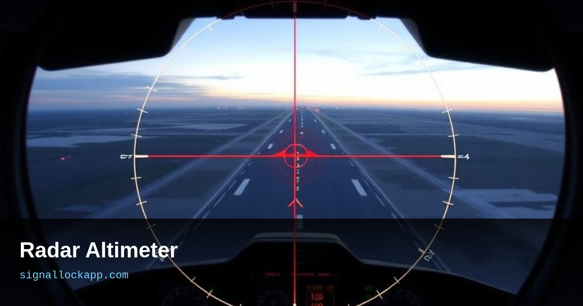
FMCW altitude measurement
Radar altimeters transmit an FMCW chirp straight down and listen for the ground bounce. Because the distance is short (tens of metres to a few kilometres), the beat frequency is low — easy to process. Accuracy is within a few centimetres, updated tens of times per second. The pilot sees a number that is true height, not an approximation.
Radio vs. barometric
Barometric altimeters are essential for separation above 2,500 ft, where everyone uses the same pressure reference. Below that, especially on final approach, radar altimeters take over. Autoland systems, terrain awareness (TAWS), and wind-shear escape manoeuvres all rely on radar altitude. The 737 MAX accidents showed how a single faulty AOA sensor can cascade; radar altimeters are equally flight-critical.
The 5G interference crisis
C-band 5G base stations in the 3.7–3.98 GHz range sit close to radar altimeter bands (4.2–4.4 GHz). Though not directly overlapping, 5G out-of-band emissions and receiver overload created real interference risks. The FAA and aviation regulators worldwide spent 2021–2023 analysing which altimeters were vulnerable and where 5G rollout had to be restricted near airports.
Next-generation altimeters
New designs use wider bandwidth, better filtering, and dual-frequency operation to reject interference. Some are exploring 60 GHz mmWave bands, far from cellular traffic, with even better precision. The mission is unchanged: tell the pilot exactly how much room is left.
The Pulse-Doppler approach for high-altitude platforms
While standard commercial aircraft utilize Frequency Modulated Continuous Wave (FMCW) for low-altitude precision, high-performance military jets and space vehicles often employ pulse-coded radar altimeters. These systems measure the time-of-flight of discrete radio pulses rather than frequency shifts. This method is superior for high-speed, high-altitude operations where the ground return might be significantly delayed or weakened by atmospheric attenuation. By analyzing the pulse compression and the leading edge of the returned signal, these altimeters can maintain lock at speeds exceeding Mach 2, providing stable data even when the terrain gradient changes rapidly under the airframe.
The shift from FMCW to pulse-based logic also mitigates 'step errors'—a common phenomenon in older analog radar altimeters where the vertical readout would jump discretely rather than transition smoothly. Modern digital signal processors (DSPs) now combine both techniques, using FMCW for the critical flare manuever below 50 feet and pulse-logic for terrain mapping at 5,000 feet. This hybrid approach ensures that the Ground Proximity Warning System (GPWS) receives high-fidelity data across the entire flight envelope, reducing the risk of Controlled Flight Into Terrain (CFIT) during high-speed low-level ingress.
Integration with Autoland and Flare Control
In a Category III (CAT III) instrument landing, the radar altimeter is not merely an advisory tool; it is the primary sensor for the aircraft's AFCS (Automatic Flight Control System). As the aircraft descends through 50 feet, the autopilot enters the 'flare' mode. Here, the radar altimeter provides the vertical descent rate data required to retard the throttles and increase the pitch attitude. Without this precision sensor, the autopilot would be unable to determine the exact moment to transition from a stabilized glide slope to a soft touchdown, potentially resulting in a hard landing or a dangerous bounce.
Crucially, the radar altimeter drives the 'minimums' callouts heard in the cockpit. Unlike barometric minimums which are subject to local pressure changes, these are absolute. Furthermore, on transport-category aircraft, the system detects 'radio altitude rate,' sensing how fast the distance to the ground is closing. If an aircraft experiences a microburst or sudden downdraft, the radar altimeter detects the increasing closure rate instantly, triggering the Reactive Windshear System (RWS) before the pilot can even register the change on the primary flight display. It is the definitive fail-safe for the final 200 feet of flight.
The Ground Proximity Warning System evolution
The integration of radar altimeters into safety systems took a significant leap following the 1974 TWA Flight 514 crash. This tragedy accelerated the FAA mandate for Ground Proximity Warning Systems (GPWS). Unlike early systems that relied on pilot awareness, GPWS uses radar altimeter data to calculate the 'closure rate' with terrain. If the rate of descent is too high relative to the actual height above ground, the system triggers a 'SINK RATE' or 'PULL UP' aural warning. Modern versions, known as Enhanced GPWS (EGPWS), compare this real-time radar data against a global digital terrain database to eliminate blind spots in mountainous areas.
A critical nuance in radar altimeter logic is the handling of landing gear and flaps configuration. The system adjusts its sensitivity based on the aircraft's phase of flight. During the cruise phase, sudden changes in terrain elevation, such as a ridge line, might trigger a nuisance alarm if the logic were too sensitive. However, during the landing flare, the system must be hyper-responsive. Sensors transmit at 4.2 to 4.4 GHz, providing precise altitude data down to the zero-foot mark. This precision allows the flight computer to retard the throttles and initiate the flare maneuver at exactly the prescribed height, typically around 50 feet above the runway threshold.
Antenna polarization and the shadowing effect
The physical installation of radar altimeter antennas is as critical as the internal circuitry. Most aircraft use a dual-antenna configuration: one for transmitting and one for receiving. These are typically flush-mounted on the underside of the fuselage to minimize drag. To prevent 'crosstalk'—where the receiver picks up the transmission directly from the Tx antenna rather than the ground—engineers use spatial separation and cross-polarization. If the antennas are too close or improperly shielded, the system may report a 'locked' altitude that reflects the distance between the antennas rather than the distance to the runway, a catastrophic failure mode during low-visibility operations.
Another technical challenge is the 'shadowing effect' during high-bank maneuvers. Because the radar beam is directed perpendicular to the aircraft's longitudinal axis, a steep bank angle can point the beam away from the ground and toward the horizon. This results in signal loss or inaccurate distance readings. To mitigate this, antennas are designed with a wide beamwidth, often up to 60 degrees, to ensure ground contact remains even during standard turns. In advanced fly-by-wire aircraft, the flight control computer compensates for the bank angle, mathematically correcting the slant range back to a vertical height to maintain flight envelope protection.